Engineering drawing is visual language of designer used to represent shape, size, view, various projections of an object, details and information about an object on Plane drawing. In most of engineering drawing we see following:
- Title block
- BOM details
- Drawing Notes
- Tolerances
- GD&T symbols
- Dimensions Different projection views
Title Block of Engineering Drawing
Title block is crucial section of drawing. Title block is kept in bottom right corner of drawing. This contains essential information about part/assembly. It includes part Name & Number, material & fit finish details, Legal owner name, Revision history and projection views.
Scale in title block show the ratio that represent the relationship between the size of the drawing and actual size of the part. The projection view is included in the title block to illustrate the entire object on a two-dimensional plane.

Apart from it drawing contain BOM – Bill of material (Child parts details), Drawing Notes – Critical information about product like testing details, etc.
Understand Drawing and Projections
Drawing projection is a technique used to represent three-dimensional objects on a two-dimensional plane. This process is essential in engineering design, ensuring that dimensions and relationships are accurately conveyed. Mastery of projection methods aids in creating precise technical drawings, enabling engineers to visualize and communicate their designs effectively.
Projections in drawing show object image from different views. Various type of view in engineering drawing is explained in end of this post.
Types of Drawing projections
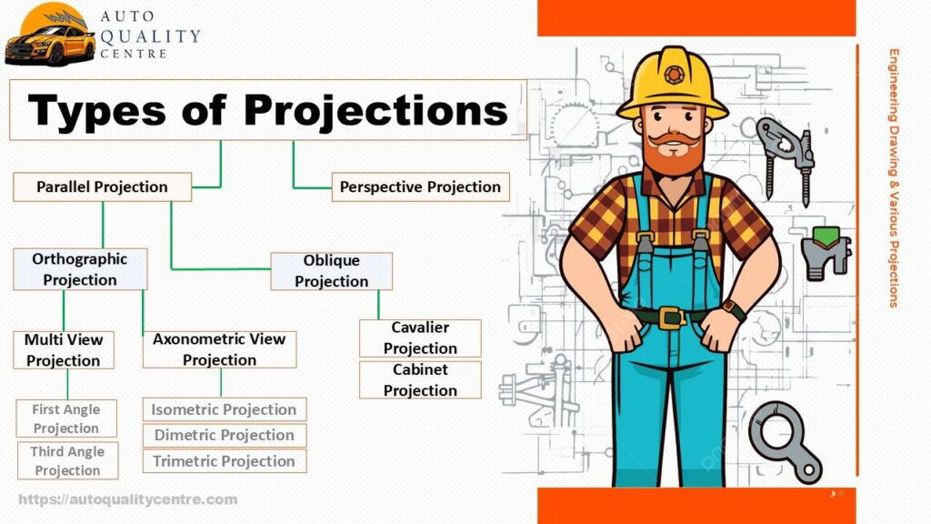
There are 2 types of drawing projection, Parallel projection and perspective projection. Further classification is done of these 2 types of projection.
1. Orthographic projection
A. Multiview projection
i. First angle projection
ii. Third angle projection
B. Axonometric view projection
i. Isometric projection
ii. Dimetric projection
iii. Trimetric projection
2. Oblique projection
- Cavalier projection
- Cabinet projection
Orthographic Projection
Orthographic projection shows a 3D object in 2D plane. Front view, Top view and Right-side view is used to represent view of 3D object on 2D drawing. Positioning of 3 views is done as per rules of first angle projection and third angle projection. In orthographic projection section view of objection is also used to represent more realistic view of object.
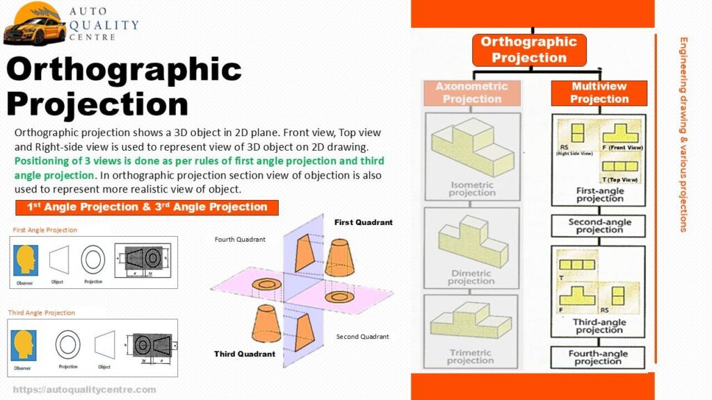
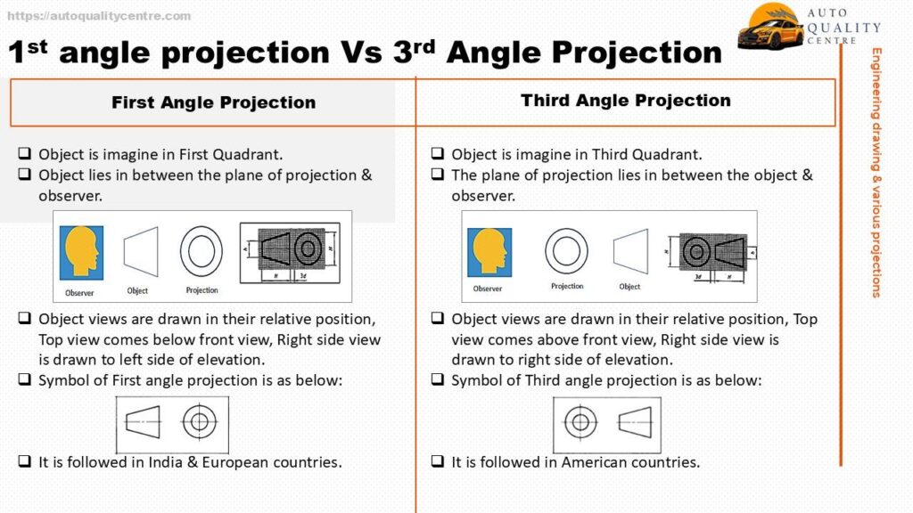
Difference between 1st angle and 3rd angle projection
- Object is imagined in First quadrant.
- Object lies in between the plane of projection & observer.
- Object views are drawn in their relative position, Top view comes below front view, Right side view is drawn to left side of elevation.
- It is followed in India & European countries.
- Object is imagined in Third quadrant.
- The plane of projection lies in between the object & observer.
- Object views are drawn in their relative position, Top view comes above front view, Right side view is drawn to right side of elevation.
- It is followed in American countries.
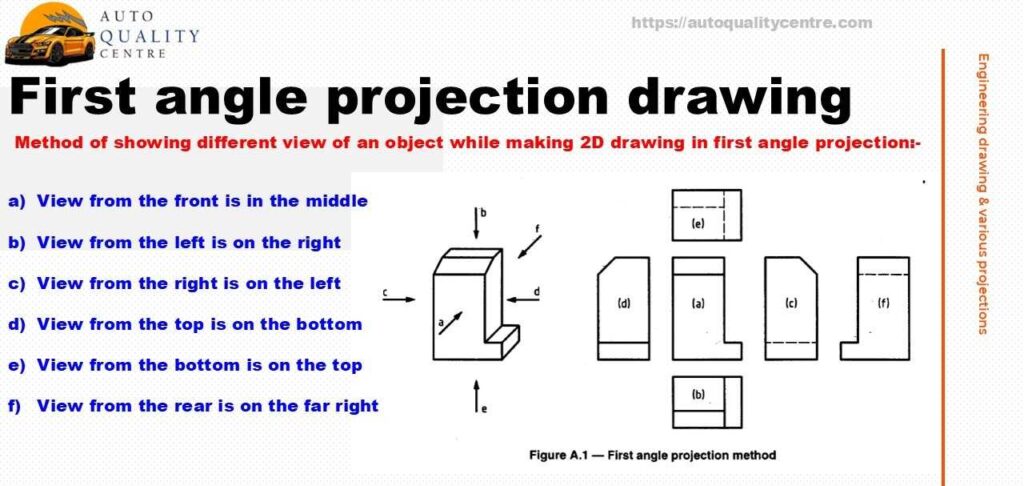
First angle projection drawing method
While drawing object on 2D plane using first angle projections, following rules are followed:
- View from the front is in the middle
- View from the left is on the right
- View from the right is on the left
- View from the top is on the bottom
- View from the bottom is on the top
- View from the rear is on the far right
Third angle projection drawing method
While drawing object on 2D plane using third angle projection, following rule are followed:
- View from the front is in the middle
- View from the left is on the left
- View from right is on the right
- View from the top is on top
- View from bottom is on bottom
- View from the rear is on the far right
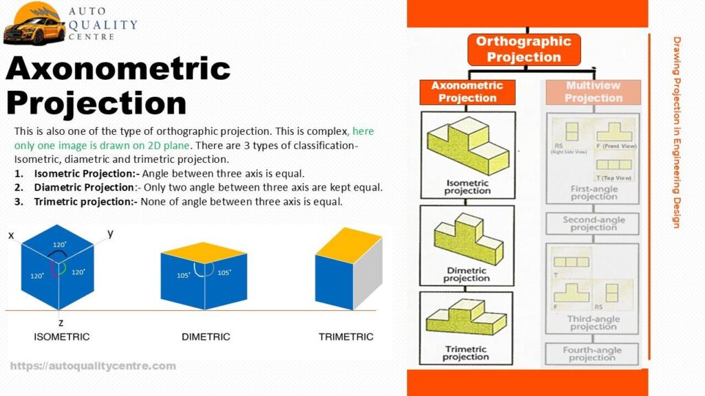
Axonometric Projection
This is also one of the type of orthographic projection. This is complex, here only one image is drawn on 2D plane. There are 3 types of classification- Isometric, diametric and trimetric projection.
- Isometric Projection: – Angle between three axes are equal.
- Diametric Projection: – Only two angles between three axes are kept equal.
- Trimetric projection: – None of angle between three axes is equal.
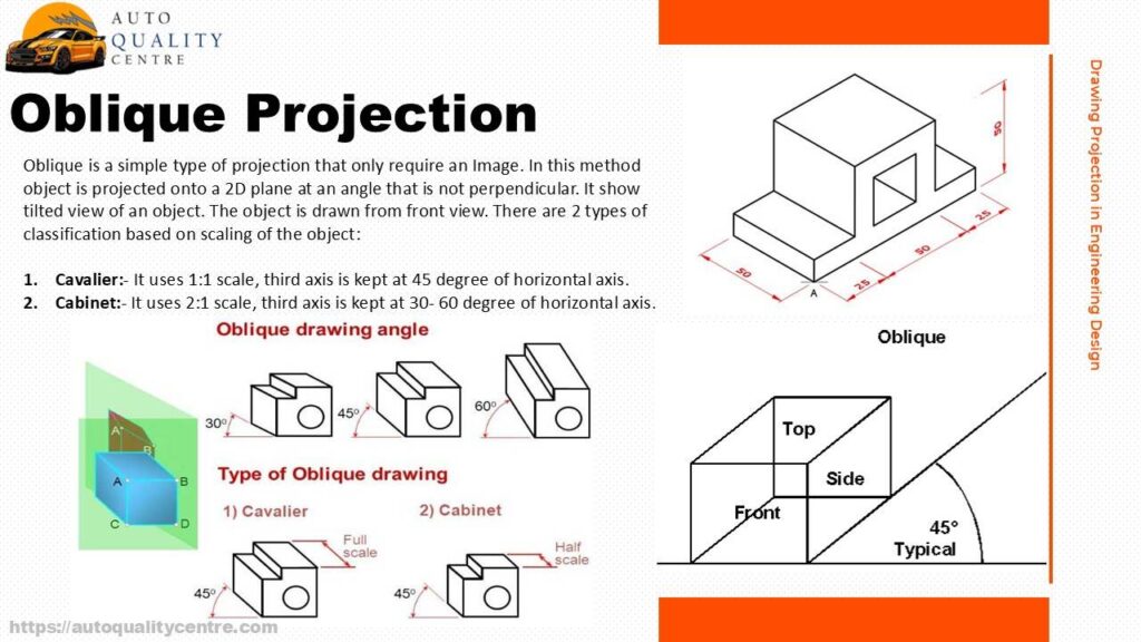
Oblique Projection
Oblique is a simple type of projection that only require an Image. In this method object is projected onto a 2D plane at an angle that is not perpendicular. It show tilted view of an object. The object is drawn from front view. There are 2 types of classification based on scaling of the object:
- Cavalier: – It uses 1:1 scale, third axis is kept at 45 degrees of horizontal axis.
- Cabinet: – It uses 2:1 scale, third axis is kept at 30- 60 degree of horizontal axis.
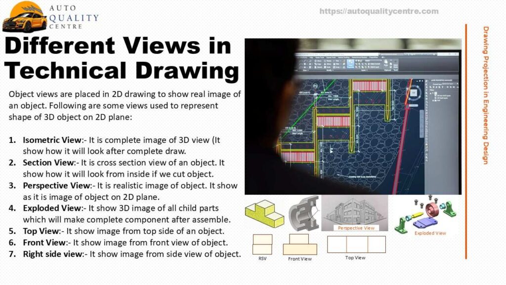
Different Views in Technical Drawing
Object views are placed in 2D drawing to show real image of an object. Following are some views used to represent shape of 3D object on 2D plane:
- Isometric View:- It is complete image of 3D view (It show how it will look after complete draw.
- Section View: – It is cross section view of an object. It shows how it will look from inside if we cut object.
- Perspective View: – It is realistic image of object. It shows as it is image of object on 2D plane.
- Exploded View: – It shows 3D image of all child parts which will make complete component after assembling.
- Top View: – It shows image from top side of an object.
- Front View: – It shows image from front view of object.
- Right side view: – It show image from side view of object.
Conclusion
Engineering drawing is widely used in industries making components. For the people working over those parts needs to know about drawing and various projection. Drawing is language of engineering talking about an object. While projection is view of an object.
Hope you like this post. Please write on contact@autoqualitycentre.com. We are happy to help you.
You may also like following post:
Scatter Diagram and stratification in 7QC tools


Pingback: Guide to implement Quality circle in Organization - AQC