Multimeter is an Electrical Testing tool. It is used to measure Current, Voltage & Resistance. It is also known as mutitester. A multimeter is a versatile instrument used to measure electrical values such as voltage (V), current (A), and resistance (Ω). It is an indispensable tool for electricians, engineers, technicians, and DIY enthusiasts working with electrical systems.
Basic understanding of electricity is required to understand uses & application of Multimeter. Here knowledge of current, type & unit of current, Voltage & its units, Capacitor & diode.
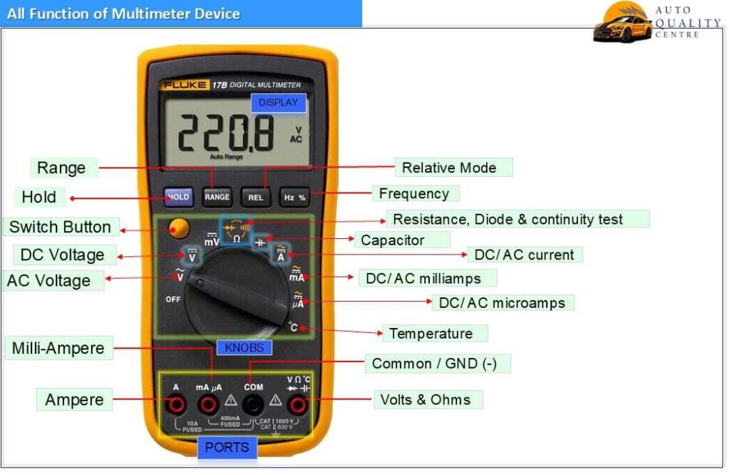
Key Function of Multimeter device
Following are key functions of Multimeter device:
- Voltage Measurement
- Current Measurement
- Resistance Measurement
- Continuity Testing
- Diode Testing
- Capacitance, Frequency, and Temperature Measurement
Other Key Function of Multimeter
Data Hold Function: – This feature allows the user to “freeze” the current reading on the screen, which is useful for capturing values in hard-to-reach places.
Range Function: – In the context of a multimeter, the range function refers to the setting or adjustment that allows you to measure a wide variety of electrical values (voltage, current, resistance, etc.) across different magnitudes. Multimeters can measure these values within a specific range, and the “range” function lets you select the appropriate scale for accurate measurements.
Relative Mode function: – The relative mode (sometimes called zeroing mode) in a multimeter is a feature that allows you to take measurements relative to a reference value, typically a value you set to “zero.” It’s especially useful when you want to measure small differences or changes in a signal or when you need to subtract a known value from a measurement.
Types of Multimeters explained
Analog Multimeter:- Displays readings via a needle and scale. Though less common today, they can provide more intuitive readings in some cases. They provide a continuous reading, which can be useful for observing fluctuating signals. Analog multimeters are less accurate than digital ones and can be harder to read. They are also more prone to mechanical damage due to their moving parts.
Digital Multimeter (DMM): Provides a numerical display, offering greater accuracy and ease of reading. These are the most widely used models today. They offer greater accuracy, ease of reading, and additional functionality compared to analog models. Digital displays eliminate the guesswork associated with interpreting needle positions. They can be more expensive and require a battery for the display.
Different application of Multimeter device
Troubleshooting Electrical Circuits: Multimeters are used to identify issues like faulty wires, malfunctioning components, and open or short circuits.
Home Electrical Work: – DIY enthusiasts can use multimeters to check the voltage of outlets, test batteries, or diagnose problems in home appliances like refrigerators or air conditioners.
Automotive Diagnostics:- Car technicians use multimeters to measure battery voltage, test alternators, and check other electrical systems in vehicles.
Electronics and Circuit Design: – Engineers and hobbyists use multimeters to test and verify components in circuits, ensuring that resistors, capacitors, transistors, and other components are functioning as expected.
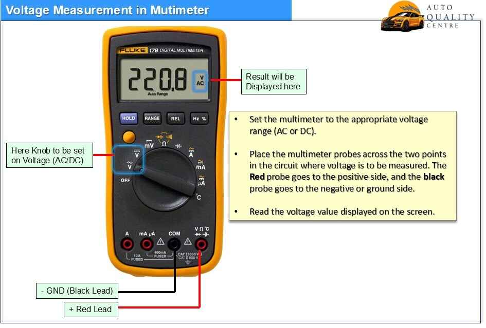
Voltage measurement by Multimeter device
Set the multimeter to the appropriate voltage range (AC or DC). Place the multimeter probes across the two points in the circuit where voltage is to be measured. The Red probe goes to the positive side, and the black probe goes to the negative or ground side.
Read the voltage value displayed on the screen.
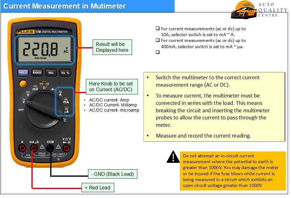
Current measurement by Multimeter device
For current measurements (ac or dc) up to 10A, selector switch is set to mA ~ A. For current measurements (ac or dc) up to 400mA, selector switch is set to mA ~ µa.
Switch the multimeter to the correct current measurement range (AC or DC).
To measure current, the multimeter must be connected in series with the load. This means breaking the circuit and inserting the multimeter probes to allow the current to pass through the meter. Measure and record the current reading.
CAUTION WARNING: – Do not attempt an in-circuit current measurement where the potential to earth is greater than 1000V. You may damage the meter or be injured if the fuse blows while current is being measured in a circuit which exhibits an open circuit voltage greater than 1000V.
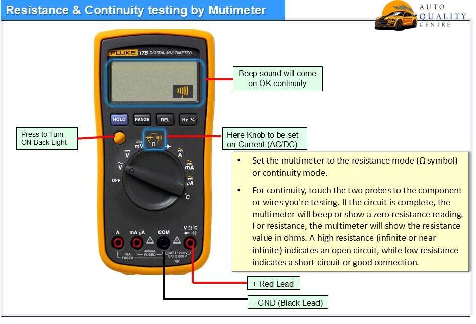
Resistance & Continuity test by Multimeter
Set the multimeter to the resistance mode (Ω symbol) or continuity mode.
For continuity, touch the two probes to the component or wires you’re testing. If the circuit is complete, the multimeter will beep or show a zero-resistance reading. For resistance, the multimeter will show the resistance value in ohms. A high resistance (infinite or near infinite) indicates an open circuit, while low resistance indicates a short circuit or good connection.
Diode and Capacitor testing by Multimeter
Capacitor Inspection: -A capacitor is an electrical component used to store energy in an electric field. It consists of two electrical conductors separated by a dielectric material that both accumulate charge when connected to a power source. One plate gets a negative charge, and the other gets a positive charge. A capacitor does not dissipate energy, unlike a resistor.
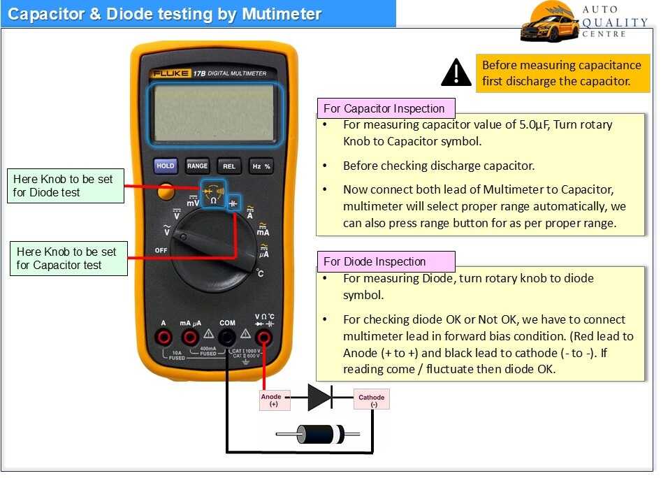
For measuring capacitor value of 5.0µF, Turn rotary Knob to Capacitor symbol.
Before checking discharge capacitor. Now connect leads of Multimeter to Capacitor, multimeter will select proper range automatically, we can also press range button for as per proper range.
How to discharge a capacitor?
It can be done simply by screwdriver. Touch metallic tip of screwdriver between 2 terminals of capacitor. For capacitor of range between more than 100V, we have to discharge with help of resistor. Simply short terminals of capacitor by resistor terminals.
Diode Inspection: – A diode is a two-terminal electronic component that allows the flow of current in only one direction. It has an anode and a cathode, and it is forward biased when it conducts current and reverse biased when it blocks current. Diodes are also called rectifiers because they can convert alternating current (ac) into direct current (dc). Diodes use a p-n junction, which is a type of semiconductor device.
Testing of diode with multimeter is done in both forward bias & reversed bias. When we connect red lead (+) with anode & black lead (-ve) with cathode then this is called positive bias, in this condition multimeter will show some reading, In LED case will show reading as well as LED will glow. Reverse of connection will be reversed bias in this case multimeter will show contact reading, indicating current is not flow in single direction (Diode is NOT OK).
For measuring Diode, turn rotary knob to diode symbol.
For checking diode OK or Not OK, we have to connect multimeter lead in forward bias condition. (Red lead to Anode (+ to +) and black lead to cathode (- to -). If reading come / fluctuate then diode OK.
Read about Latest PFMEA based on AIAG+VDA


Pingback: Poka Yoke Types and its basic Function - AQC
Pingback: Know all about 5S, 3M, 3K, 3G Terminology - AQC